Solutions
Explanation:
Maximum shear stress theory
(Guest & Tresca’s Theory)
According to this theory, failure of the specimen subjected to any combination of a load when the maximum shearing stress at any point reaches the failure value equal to that developed at the yielding in an axial tensile or compressive test of the same material.
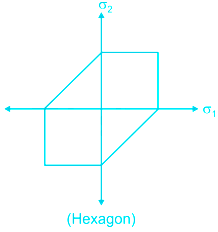
Graphical Representation
For no failure
For design
σ1 and σ2 are maximum and minimum principal stress respectively.
Here, τmax = Maximum shear stress
σy = permissible stress
This theory is well justified for ductile materials.
Maximum shear strain energy / Distortion energy theory / Mises – Henky theory.
It states that inelastic action at any point in body, under any combination of stress begging, when the strain energy of distortion per unit volume absorbed at the point is equal to the strain energy of distortion absorbed per unit volume at any point in a bar stressed to the elastic limit under the state of uniaxial stress as occurs in a simple tension/compression test.
for no failure
For design
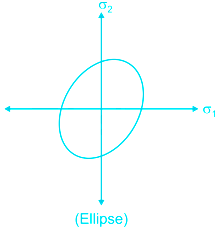
It cannot be applied for material under hydrostatic pressure.
All theories will give the same results if loading is uniaxial.
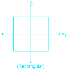
Maximum principal stress theory (Rankine’s theory)
According to this theory, the permanent set takes place under a state of complex stress, when the value of maximum principal stress is equal to that of yield point stress as found in a simple tensile test.
For the design criterion, the maximum principal stress (σ1) must not exceed the working stress ‘σy’ for the material.
for no failure
for design
Note: For no shear failure τ ≤ 0.57 σy
Graphical representation
For brittle material, which does not fail by yielding but fail by brittle fracture, this theory gives a satisfactory result.
The graph is always square even for different values of σ1 and σ2.
![]()
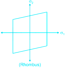
Maximum principal strain theory (ST. Venant’s theory)
According to this theory, a ductile material begins to yield when the maximum principal strain reaches the strain at which yielding occurs in simple tension.
For no failure in uniaxial loading.
For no failure in triaxial loading.
For design, Here, ϵ = Principal strain
σ1, σ2, and σ3 = Principal stresses
Graphical Representation
This theory overestimates the elastic strength of ductile material.
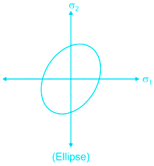
Maximum strain energy theory (Haigh’s theory)
According to this theory, a body complex stress fails when the total strain energy at the elastic limit in simple tension.
Graphical Representation.
for no failure
for design
This theory does not apply to brittle material for which elastic limit stress in tension and in compression are quite different.


 Time Taken: -


 ×
×
 Bank
Bank


 SSC
SSC


 Railway


 State
State


 Other
Other


 Teaching


 Insurance


 Medical


 Engineering


 Defence


 GATE
GATE


 NTA CUET

 UPSC
UPSC

 MBA Entrance


 AIIMS Nursing Officer (NORCET - 8) 2025
 NDA I 2025
 CDS I 2025
 JEE Main 2025 : Session 2
 NEET UG 2025
 CUET UG 2025
 RRB NTPC 2024-25
 Railway Group D 2025
 Bihar Police Constable 2025


